
This is Part 4 of an eight-part series describing how to design a database for a Workflow Engine. Check out Part 1 here:
 Matthew Jones
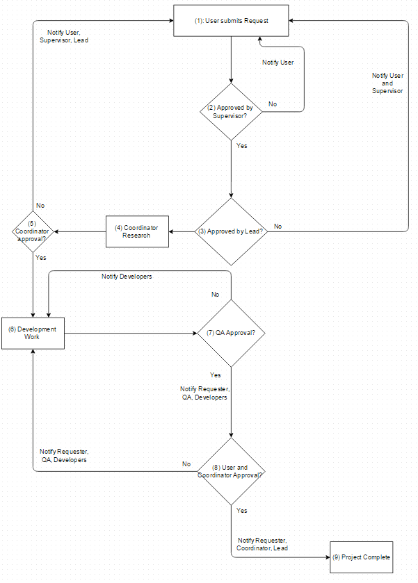
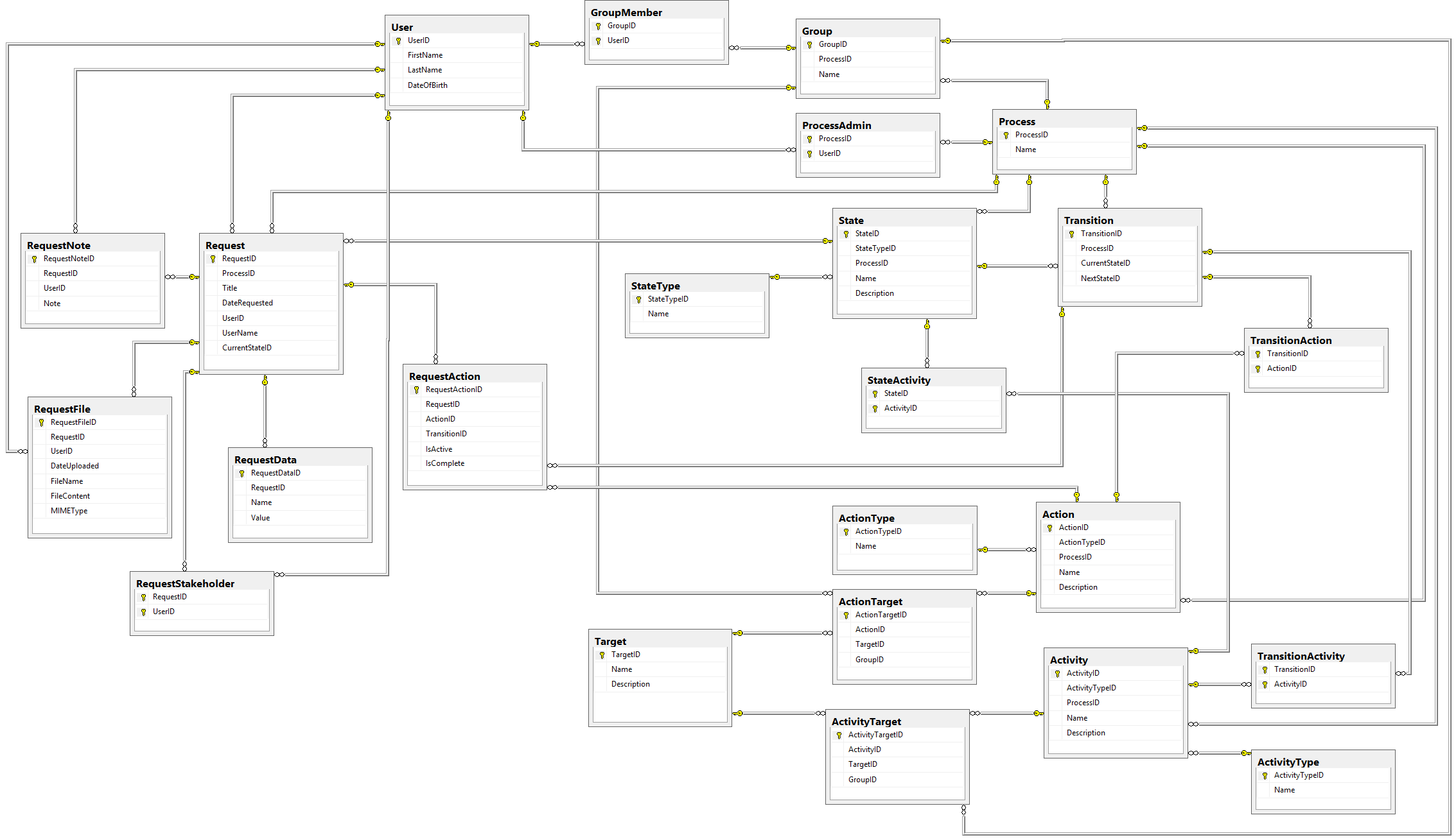
Now that we've got the Process and Request tables created, we can start building tables for the actual process itself.
In this part of our series, we'll design the tables that will hold the different States a Request can be in as part of a Process, and we'll also design the tables that show how to get from one State to another (which are called Transitions). First, though, we need a table that shows what different types of States can exist.
Let's get started!
State Types
A State Type is a categorization of the individual States. In our design, it is a unchangeable list, so in code we would probably use an Enumeration to represent it. Since we're making this database design fully-normalized, we're going to include this set of data as a table, with the following structure:
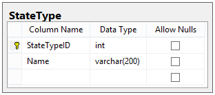
Because we don't want to have any user-defined State Types, there's no relationship to Process for this table. We're treating this table as unchangeable, and will always have the following values:
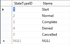
Here's the reasoning for each of these types:
- Start: Should only be one per process. This state is the state into which a new Request is placed when it is created.
- Normal: A regular state with no special designation.
- Complete: A state signifying that any Request in this state have completed normally.
- Denied: A state signifying that any Request in this state has been denied (e.g. never got started and will not be worked on).
- Cancelled: A state signifying that any Request in this state has been cancelled (e.g. work was started but never completed).
Every State must have exactly one of these State Types. But what makes a State?
States
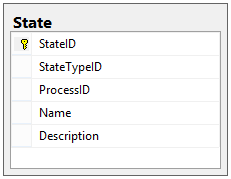
A State is a position in the Process that a given Request can be in at any given moment. States are unique to Processes, and each State has a name, a description, and a type. Our State table looks like this:
We should remember, though, that each Process is supposed to represent a flow chart, and to do that we need to be able to move Requests between the States. We can do so by designing tables for Transitions.
Transitions
If a the lead developer approves a request, and it should now go to the Coordinator team for research, how can we design our data so as to represent that that move is possible? We create a Transition.
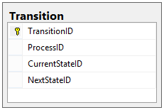
A Transition is a path between two States that shows how a Request can travel between them. Transitions are unique to Processes, and therefore a Transition is comprised of a primary key, a Process ID, a current state, and a next state:
What did we accomplish?
Our current database design (showing only States, Transitions, and Process tables) looks something like this:
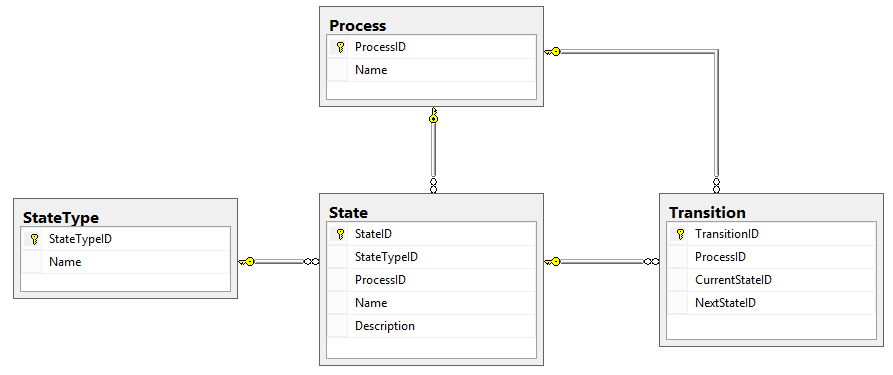
In this post, we gave form to the building blocks of the Process by defining the States where a Request can exist and the Transitions between those States.
We still have an outstanding problem, though: how do we invoke our Transitions? How do we actually cause a Request to move from one State to another? And what should happen each time we go to a new State (or follow a new Transition) for a given Request?
All that and more in the next post, Part 5 of this adventure, which discusses Actions and Activities.
Matthew Jones
Happy Coding!